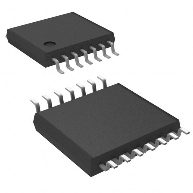
SN74LVC74APWRG4
Overview
- Category: Integrated Circuit
- Use: Flip-Flop
- Characteristics: Low-Voltage, CMOS Logic, Dual D-Type Positive-Edge-Triggered Flip-Flop
- Package: TSSOP (Thin Shrink Small Outline Package)
- Essence: Sequential Logic Device
- Packaging/Quantity: Tape and Reel, 2500 pieces per reel
Specifications
- Supply Voltage Range: 1.65V to 5.5V
- High-Level Input Voltage: 2V to VCC + 0.5V
- Low-Level Input Voltage: -0.5V to 0.8V
- High-Level Output Voltage: VCC - 0.5V
- Low-Level Output Voltage: 0.5V
- Maximum Operating Frequency: 100MHz
- Propagation Delay Time: 3.7ns
- Set-Up Time: 1.5ns
- Hold Time: 0.9ns
Pin Configuration
The SN74LVC74APWRG4 has a total of 14 pins. The pin configuration is as follows:
- CLR (Clear) - Active-Low Clear Input
- D (Data) - Data Input
- CLK (Clock) - Clock Input
- PR (Preset) - Active-Low Preset Input
- Q (Output) - Output
- Q̅ (Complementary Output) - Complementary Output
- GND (Ground) - Ground
- Q̅ (Complementary Output) - Complementary Output
- Q (Output) - Output
- VCC (Positive Power Supply) - Positive Power Supply
- D (Data) - Data Input
- CLK (Clock) - Clock Input
- PR (Preset) - Active-Low Preset Input
- CLR (Clear) - Active-Low Clear Input
Functional Features
The SN74LVC74APWRG4 is a dual D-type positive-edge-triggered flip-flop. It operates at low voltage levels and utilizes CMOS logic. The device has two independent flip-flops with individual clear, preset, clock, and data inputs. The flip-flop outputs are complementary to each other.
Advantages and Disadvantages
Advantages: - Low-voltage operation allows for compatibility with various systems. - CMOS logic provides low power consumption. - Dual flip-flop configuration offers flexibility in sequential logic design.
Disadvantages: - Limited maximum operating frequency compared to some other flip-flop models. - Propagation delay time may impact timing-critical applications.
Working Principles
The SN74LVC74APWRG4 operates based on the positive-edge-triggered flip-flop principle. When the clock input (CLK) receives a rising edge, the data input (D) is transferred to the output (Q) and its complement (Q̅). The clear (CLR) and preset (PR) inputs allow for resetting or setting the flip-flop outputs to specific states.
Detailed Application Field Plans
The SN74LVC74APWRG4 is commonly used in various digital systems and applications, including but not limited to: - Microcontrollers - Data storage devices - Communication systems - Signal processing circuits - Control systems
Alternative Models
If the SN74LVC74APWRG4 does not meet specific requirements, alternative models that can be considered include: - SN74LV74A: Similar functionality, but operates at a higher voltage range. - CD4013B: Dual D-type flip-flop with different characteristics and package options. - MC74HC74A: High-speed CMOS logic flip-flop with similar pin configuration.
These alternative models provide different voltage ranges, speed, and package options to suit various design needs.
In conclusion, the SN74LVC74APWRG4 is a low-voltage, CMOS logic dual D-type positive-edge-triggered flip-flop. It offers flexibility in sequential logic design and finds applications in various digital systems. Designers can consider alternative models if specific requirements are not met by this particular device.
רשום 10 שאלות ותשובות נפוצות הקשורות ליישום של SN74LVC74APWRG4 בפתרונות טכניים
Sure! Here are 10 common questions and answers related to the application of SN74LVC74APWRG4:
Q: What is the SN74LVC74APWRG4? A: The SN74LVC74APWRG4 is a dual D-type flip-flop integrated circuit (IC) that can store one bit of data.
Q: What is the operating voltage range for SN74LVC74APWRG4? A: The operating voltage range for SN74LVC74APWRG4 is typically between 1.65V and 5.5V.
Q: What is the maximum clock frequency supported by SN74LVC74APWRG4? A: SN74LVC74APWRG4 can support clock frequencies up to 100 MHz.
Q: How many flip-flops are there in SN74LVC74APWRG4? A: SN74LVC74APWRG4 contains two independent D-type flip-flops.
Q: What is the output drive strength of SN74LVC74APWRG4? A: The output drive strength of SN74LVC74APWRG4 is typically 24 mA.
Q: Can SN74LVC74APWRG4 be used in both synchronous and asynchronous applications? A: Yes, SN74LVC74APWRG4 can be used in both synchronous and asynchronous applications.
Q: What is the propagation delay of SN74LVC74APWRG4? A: The propagation delay of SN74LVC74APWRG4 is typically around 4.8 ns.
Q: Is SN74LVC74APWRG4 compatible with other logic families? A: Yes, SN74LVC74APWRG4 is compatible with both 3.3V and 5V logic families.
Q: Can SN74LVC74APWRG4 be used in high-speed data transfer applications? A: Yes, SN74LVC74APWRG4 can be used in high-speed data transfer applications due to its fast switching speed.
Q: What are some common applications of SN74LVC74APWRG4? A: SN74LVC74APWRG4 is commonly used in digital systems, such as microcontrollers, memory interfaces, and communication devices, for data storage and synchronization purposes.
Please note that the answers provided here are general and may vary depending on specific datasheet specifications and application requirements.


