

SN74HCT574DBR
Product Overview
- Category: Integrated Circuit
- Use: Flip-Flop
- Characteristics: High-speed, CMOS technology
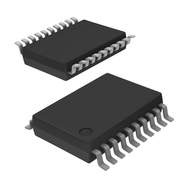
- Package: SSOP-20
- Essence: Octal D-type flip-flop with 3-state outputs
- Packaging/Quantity: Tape and Reel, 2500 pieces per reel
Specifications
- Supply Voltage Range: 4.5V to 5.5V
- Input Voltage Range: 0V to VCC
- Output Voltage Range: 0V to VCC
- Operating Temperature Range: -40°C to +85°C
- Propagation Delay Time: 15ns (typical)
- Output Current: ±6mA
- Input Capacitance: 3pF (typical)
Detailed Pin Configuration
The SN74HCT574DBR has a total of 20 pins. The pin configuration is as follows:
- GND (Ground)
- D0 (Data input 0)
- D1 (Data input 1)
- D2 (Data input 2)
- D3 (Data input 3)
- D4 (Data input 4)
- D5 (Data input 5)
- D6 (Data input 6)
- D7 (Data input 7)
- OE (Output enable)
- CP (Clock pulse)
- MR (Master reset)
- Q0 (Flip-flop output 0)
- Q1 (Flip-flop output 1)
- Q2 (Flip-flop output 2)
- Q3 (Flip-flop output 3)
- Q4 (Flip-flop output 4)
- Q5 (Flip-flop output 5)
- Q6 (Flip-flop output 6)
- VCC (Power supply)
Functional Features
The SN74HCT574DBR is an octal D-type flip-flop with 3-state outputs. It features a high-speed operation and utilizes CMOS technology. The flip-flop has a master reset function and an output enable control, allowing for flexible data storage and retrieval.
Advantages and Disadvantages
Advantages: - High-speed operation - CMOS technology for low power consumption - 3-state outputs for bus-oriented applications - Master reset function for easy initialization
Disadvantages: - Limited voltage range (4.5V to 5.5V) - Relatively small input capacitance (3pF)
Working Principles
The SN74HCT574DBR operates based on the principles of D-type flip-flops. It stores and transfers data using clock pulses and enables or disables the output using the output enable control. The master reset function allows for resetting all flip-flops simultaneously.
Detailed Application Field Plans
The SN74HCT574DBR is commonly used in various digital systems and applications, including but not limited to:
- Data storage and retrieval in microcontrollers
- Address decoding in memory systems
- Bus-oriented systems requiring 3-state outputs
- Serial-to-parallel and parallel-to-serial data conversion
- Control and synchronization circuits in communication systems
Detailed and Complete Alternative Models
- SN74HCT574N: DIP-20 package, through-hole mounting
- MC74HCT574AN: PDIP-20 package, through-hole mounting
- CD74HCT574E: PDIP-20 package, through-hole mounting
- 74HCT574D: SOIC-20 package, surface-mounting
- TC74HCT574AF: TSSOP-20 package, surface-mounting
These alternative models offer similar functionality and can be used as substitutes for the SN74HCT574DBR in various applications.
In conclusion, the SN74HCT574DBR is a high-speed octal D-type flip-flop with 3-state outputs. It is widely used in digital systems for data storage, address decoding, and synchronization purposes. Its advantages include high-speed operation, low power consumption, and flexible control features. However, it has limitations in terms of voltage range and input capacitance. Alternative models are available to suit different packaging and mounting requirements.
רשום 10 שאלות ותשובות נפוצות הקשורות ליישום של SN74HCT574DBR בפתרונות טכניים
Sure! Here are 10 common questions and answers related to the application of SN74HCT574DBR:
Q: What is the SN74HCT574DBR? A: The SN74HCT574DBR is a high-speed octal D-type flip-flop with 3-state outputs, commonly used in digital systems.
Q: What is the maximum operating voltage for the SN74HCT574DBR? A: The SN74HCT574DBR has a maximum operating voltage of 5.5V.
Q: How many flip-flops are there in the SN74HCT574DBR? A: The SN74HCT574DBR consists of 8 individual D-type flip-flops.
Q: What is the output current capability of the SN74HCT574DBR? A: The SN74HCT574DBR has a typical output current capability of ±6mA.
Q: Can the SN74HCT574DBR be used for level shifting? A: Yes, the SN74HCT574DBR can be used for level shifting as it supports both TTL and CMOS logic levels.
Q: What is the propagation delay of the SN74HCT574DBR? A: The propagation delay of the SN74HCT574DBR is typically around 11ns.
Q: Does the SN74HCT574DBR have an internal clock? A: No, the SN74HCT574DBR does not have an internal clock. It relies on an external clock signal.
Q: Can the SN74HCT574DBR be cascaded to increase the number of flip-flops? A: Yes, multiple SN74HCT574DBR chips can be cascaded together to increase the number of flip-flops in a system.
Q: What is the power supply voltage range for the SN74HCT574DBR? A: The power supply voltage range for the SN74HCT574DBR is typically between 4.5V and 5.5V.
Q: Can the outputs of the SN74HCT574DBR be tri-stated? A: Yes, the outputs of the SN74HCT574DBR can be tri-stated using the OE (Output Enable) pin.
Please note that these answers are general and may vary depending on specific datasheet specifications and application requirements.