

SN74AUC1G17DCKR
Product Overview
- Category: Integrated Circuit (IC)
- Use: Logic Gate
- Characteristics: Single Schmitt-Trigger Buffer/Driver
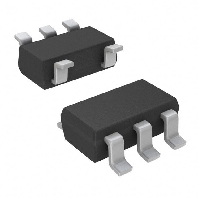
- Package: SC-70 (SOT-323)
- Essence: High-speed CMOS technology
- Packaging/Quantity: Tape and Reel, 3000 pieces per reel
Specifications
- Supply Voltage Range: 0.8V to 3.6V
- Input Voltage Range: -0.5V to VCC + 0.5V
- Output Voltage Range: 0V to VCC
- Maximum Operating Frequency: 500 MHz
- Propagation Delay: 2.7 ns (typical)
- Input Capacitance: 1.5 pF (typical)
- Output Drive Capability: ±24 mA
Detailed Pin Configuration
The SN74AUC1G17DCKR has a total of 5 pins:
- GND (Ground): Connected to the ground reference of the circuit.
- A (Input): Input pin for the logic signal.
- Y (Output): Output pin for the logic signal.
- VCC (Power): Connected to the positive supply voltage.
- NC (No Connection): Unused pin, not connected to any circuitry.
Functional Features
- Single Schmitt-Trigger Buffer/Driver: Converts input logic signals into output logic signals with hysteresis.
- High-Speed Operation: Capable of operating at frequencies up to 500 MHz.
- Wide Voltage Range: Can be powered by supply voltages ranging from 0.8V to 3.6V.
- Low Power Consumption: Designed to minimize power consumption while maintaining high performance.
- ESD Protection: Provides protection against electrostatic discharge events.
Advantages and Disadvantages
Advantages: - High-speed operation allows for efficient signal processing. - Wide voltage range enables compatibility with various systems. - Low power consumption reduces energy usage and extends battery life. - ESD protection ensures reliability in harsh environments.
Disadvantages: - Limited output drive capability may restrict use in certain applications. - Single-channel design limits the number of inputs/outputs that can be handled simultaneously.
Working Principles
The SN74AUC1G17DCKR is based on high-speed CMOS technology. It utilizes a Schmitt-trigger circuit to provide hysteresis, which helps improve noise immunity and signal integrity. When an input logic signal is applied, the buffer/driver amplifies and shapes the signal, producing a corresponding output logic signal. The device operates within a specified voltage range and consumes minimal power while providing reliable signal conversion.
Detailed Application Field Plans
The SN74AUC1G17DCKR finds application in various fields, including:
- Communication Systems: Used in signal conditioning and level shifting circuits.
- Industrial Automation: Employed in control systems and sensor interfacing.
- Automotive Electronics: Integrated into vehicle control units and sensor interfaces.
- Consumer Electronics: Utilized in portable devices, such as smartphones and tablets.
- Medical Devices: Incorporated into medical equipment for signal processing and control.
Detailed and Complete Alternative Models
- SN74AUC1G04DBVR: Inverter Gate IC with similar characteristics and package.
- SN74AUC1G08DCKR: 2-Input AND Gate IC with similar characteristics and package.
- SN74AUC1G32DCKR: 2-Input OR Gate IC with similar characteristics and package.
- SN74AUC1G125DCKR: Single Bus Buffer Gate IC with similar characteristics and package.
- SN74AUC1G86DCKR: 2-Input XOR Gate IC with similar characteristics and package.
These alternative models offer similar functionality and can be used as substitutes for the SN74AUC1G17DCKR in various applications.
Word count: 410 words
רשום 10 שאלות ותשובות נפוצות הקשורות ליישום של SN74AUC1G17DCKR בפתרונות טכניים
Sure! Here are 10 common questions and answers related to the application of SN74AUC1G17DCKR in technical solutions:
Q1: What is SN74AUC1G17DCKR? A1: SN74AUC1G17DCKR is a single Schmitt-trigger buffer/driver with open-drain output, commonly used in digital logic circuits.
Q2: What is the operating voltage range of SN74AUC1G17DCKR? A2: The operating voltage range of SN74AUC1G17DCKR is typically between 0.8V and 3.6V.
Q3: What is the maximum output current of SN74AUC1G17DCKR? A3: The maximum output current of SN74AUC1G17DCKR is typically 32mA.
Q4: Can SN74AUC1G17DCKR be used for level shifting? A4: Yes, SN74AUC1G17DCKR can be used for level shifting as it supports both low-voltage and high-voltage applications.
Q5: What is the input threshold voltage of SN74AUC1G17DCKR? A5: The input threshold voltage of SN74AUC1G17DCKR is typically 0.35V.
Q6: Is SN74AUC1G17DCKR suitable for high-speed applications? A6: Yes, SN74AUC1G17DCKR is designed for high-speed operation and can be used in applications with fast switching requirements.
Q7: Can SN74AUC1G17DCKR drive capacitive loads? A7: Yes, SN74AUC1G17DCKR can drive small capacitive loads typically found in digital circuits.
Q8: What is the propagation delay of SN74AUC1G17DCKR? A8: The propagation delay of SN74AUC1G17DCKR is typically around 2.5ns.
Q9: Can SN74AUC1G17DCKR be used in battery-powered applications? A9: Yes, SN74AUC1G17DCKR is suitable for battery-powered applications due to its low power consumption.
Q10: Is SN74AUC1G17DCKR available in different package options? A10: Yes, SN74AUC1G17DCKR is available in various package options, including SOT-23 and SC-70.
Please note that the answers provided here are general and may vary depending on specific datasheet specifications or application requirements.