

PCF8575PWRE4
Product Overview
- Category: Integrated Circuit (IC)
- Use: I/O Expander
- Characteristics: 16-bit remote I/O expander for I2C-bus with interrupt
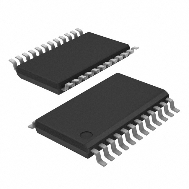
- Package: TSSOP (Thin Shrink Small Outline Package)
- Essence: The PCF8575PWRE4 is a versatile integrated circuit that expands the number of input/output (I/O) pins available to a microcontroller or microprocessor. It communicates with the host device through the I2C-bus protocol and provides 16 additional I/O lines.
- Packaging/Quantity: The PCF8575PWRE4 is typically sold in reels or tubes, containing a specific quantity of ICs per package.
Specifications
- Supply Voltage Range: 2.5V to 6V
- Input/Output Voltage Range: 0V to VDD
- Maximum Output Current: 25mA per I/O pin
- Operating Temperature Range: -40°C to +85°C
- I2C-bus Interface: Compatible with Standard-mode, Fast-mode, and Fast-mode Plus
Detailed Pin Configuration
The PCF8575PWRE4 has a total of 24 pins, which are assigned as follows:
- A0: Address Input Bit 0
- A1: Address Input Bit 1
- A2: Address Input Bit 2
- SDA: Serial Data Line (I2C-bus)
- SCL: Serial Clock Line (I2C-bus)
- INT: Interrupt Output
- P7-P0: I/O Port 0-7
- P15-P8: I/O Port 8-15
- VSS: Ground
- VDD: Supply Voltage
Functional Features
- Remote I/O Expansion: The PCF8575PWRE4 allows for easy expansion of I/O lines, enabling the connection of multiple devices to a single microcontroller.
- Interrupt Functionality: The integrated interrupt output (INT) can be used to notify the host device when a change in the input status occurs, reducing the need for continuous polling.
- Low Power Consumption: The IC is designed to operate with low power consumption, making it suitable for battery-powered applications.
- I2C-bus Compatibility: The PCF8575PWRE4 supports various I2C-bus modes, allowing for seamless integration into existing systems.
Advantages and Disadvantages
Advantages: - Increased I/O Capability: Provides 16 additional I/O lines, expanding the connectivity options for microcontrollers. - Simplified Design: Reduces the need for complex wiring and external components by consolidating multiple devices into one IC. - Interrupt Functionality: Allows for efficient event-driven programming and reduces the burden on the host device.
Disadvantages: - Limited Output Current: Each I/O pin has a maximum output current of 25mA, which may not be sufficient for certain high-power applications. - I2C-bus Dependency: The PCF8575PWRE4 relies on the I2C-bus protocol for communication, which may introduce additional complexity in system design.
Working Principles
The PCF8575PWRE4 operates as an I/O expander by utilizing the I2C-bus protocol. It communicates with the host device (microcontroller or microprocessor) through the SDA (Serial Data Line) and SCL (Serial Clock Line) pins. The address inputs (A0, A1, A2) allow for multiple PCF8575PWRE4 devices to be connected to the same bus, providing expanded I/O capabilities.
The I/O ports (P0-P15) can be configured as either inputs or outputs. The state of the input pins can be read by the host device, while the output pins can be controlled to drive external devices. The interrupt output (INT) pin can be used to signal the host device when a change in the input status occurs, reducing the need for continuous polling.
Detailed Application Field Plans
The PCF8575PWRE4 finds applications in various fields, including:
- Industrial Automation: Used to expand the I/O capabilities of programmable logic controllers (PLCs) and industrial control systems.
- Home Automation: Enables the connection of multiple sensors, actuators, and peripheral devices to a central home automation controller.
- Automotive Electronics: Provides additional I/O lines for automotive control units, allowing for enhanced functionality and connectivity.
- Internet of Things (IoT): Facilitates the integration of sensors and actuators into IoT devices, enabling data collection and remote control.
Detailed and Complete Alternative Models
- MCP23017: 16-Bit I/O Expander with Serial Interface
- MAX7313: 16-Port I/O Expander with LED Intensity Control
- PCA
רשום 10 שאלות ותשובות נפוצות הקשורות ליישום של PCF8575PWRE4 בפתרונות טכניים
Sure! Here are 10 common questions and answers related to the application of PCF8575PWRE4:
Q: What is PCF8575PWRE4? A: PCF8575PWRE4 is an I/O expander integrated circuit (IC) that provides additional input/output ports for microcontrollers or other digital devices.
Q: How many I/O ports does PCF8575PWRE4 have? A: PCF8575PWRE4 has a total of 16 I/O ports, which can be configured as either inputs or outputs.
Q: What is the voltage range supported by PCF8575PWRE4? A: PCF8575PWRE4 supports a voltage range of 2.3V to 5.5V, making it compatible with a wide range of microcontrollers and digital devices.
Q: Can PCF8575PWRE4 handle both analog and digital signals? A: No, PCF8575PWRE4 is designed to handle only digital signals. It cannot process analog signals directly.
Q: How do I communicate with PCF8575PWRE4? A: PCF8575PWRE4 uses the I2C communication protocol, allowing you to control and read the status of its I/O ports using just two wires.
Q: Can I use multiple PCF8575PWRE4 ICs in my project? A: Yes, you can connect multiple PCF8575PWRE4 ICs together on the same I2C bus, allowing you to expand the number of available I/O ports.
Q: What is the maximum current that each I/O port of PCF8575PWRE4 can sink/source? A: Each I/O port of PCF8575PWRE4 can sink/source up to 25mA of current, making it suitable for driving LEDs, relays, and other low-power devices.
Q: Can PCF8575PWRE4 be used with both 3.3V and 5V microcontrollers? A: Yes, PCF8575PWRE4 is compatible with both 3.3V and 5V microcontrollers, thanks to its wide voltage range support.
Q: Is PCF8575PWRE4 capable of interrupt-based I/O operations? A: No, PCF8575PWRE4 does not have built-in interrupt functionality. However, you can use polling techniques to check the status of its I/O ports periodically.
Q: Are there any limitations or considerations when using PCF8575PWRE4? A: One important consideration is that PCF8575PWRE4 operates at a relatively slow speed compared to some other ICs. Additionally, it is important to ensure proper decoupling and grounding to minimize noise and interference.
Please note that these answers are general and may vary depending on specific application requirements and datasheet specifications.