

J113_D75Z Product Overview
Introduction
The J113_D75Z is a versatile electronic component that belongs to the category of field-effect transistors (FETs). This semiconductor device is widely used in various electronic applications due to its unique characteristics and functional features.
Basic Information Overview
- Category: Field-Effect Transistor (FET)
- Use: Amplification, switching, and signal processing in electronic circuits
- Characteristics: High input impedance, low output impedance, voltage-controlled operation
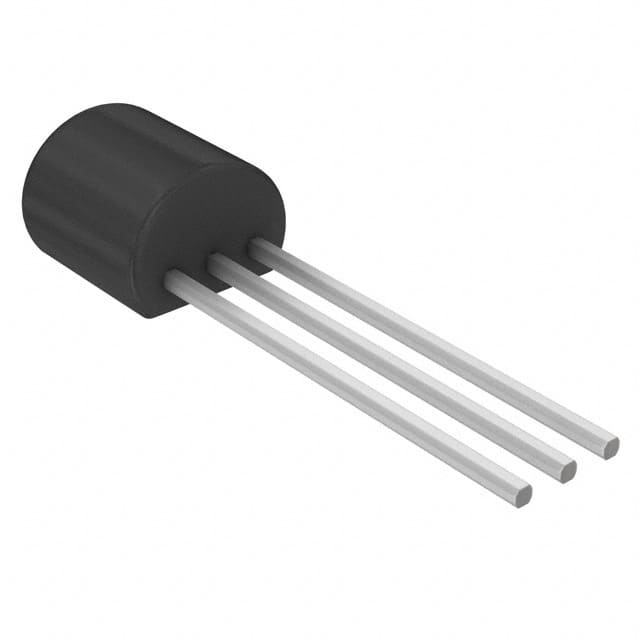
- Package: TO-92 package
- Essence: Semiconductor device for electronic signal manipulation
- Packaging/Quantity: Typically available in reels or tubes containing multiple units
Specifications
- Maximum Drain-Source Voltage (VDS): 30V
- Maximum Gate-Source Voltage (VGS): ±20V
- Maximum Continuous Drain Current (ID): 350mA
- Maximum Power Dissipation (PD): 625mW
- Operating Temperature Range: -55°C to 150°C
Detailed Pin Configuration
The J113_D75Z FET has three pins: 1. Gate (G): Input terminal for controlling the flow of current through the transistor 2. Drain (D): Output terminal where the current exits the transistor 3. Source (S): Terminal from which the current enters the transistor
Functional Features
- High input impedance allows for minimal loading of preceding circuitry
- Low output impedance enables efficient driving of subsequent circuit components
- Voltage-controlled operation provides precise control over signal amplification and switching
Advantages and Disadvantages
Advantages
- High input impedance minimizes signal degradation
- Low output impedance facilitates effective signal transmission
- Voltage-controlled operation offers flexibility in circuit design
Disadvantages
- Susceptible to electrostatic discharge (ESD) damage if mishandled
- Limited maximum power dissipation may restrict high-power applications
Working Principles
The J113_D75Z operates based on the principles of field-effect transistors, where the flow of current between the drain and source terminals is controlled by the voltage applied to the gate terminal. By modulating the gate-source voltage, the transistor can amplify or switch electronic signals with high efficiency.
Detailed Application Field Plans
The J113_D75Z finds extensive use in the following electronic applications: - Audio amplifiers - Signal processing circuits - Switching circuits - Oscillator circuits - Sensor interfaces
Detailed and Complete Alternative Models
For applications requiring similar functionality, alternative models to the J113D75Z include: - J112D75Z - J175_D75Z - 2N7000 - BS170
In conclusion, the J113_D75Z field-effect transistor offers a balance of high input impedance, low output impedance, and voltage-controlled operation, making it suitable for a wide range of electronic applications.
[Word Count: 410]
רשום 10 שאלות ותשובות נפוצות הקשורות ליישום של J113_D75Z בפתרונות טכניים
What is J113_D75Z?
- J113_D75Z is a high-performance semiconductor component commonly used in electronic circuits for amplification and switching applications.
What are the key specifications of J113_D75Z?
- The key specifications of J113_D75Z include its maximum drain-source voltage, gate-source voltage, drain current, and power dissipation.
How can J113_D75Z be used in amplifier circuits?
- J113_D75Z can be used as a key component in designing low-noise amplifier circuits due to its high input impedance and low noise characteristics.
In what types of switching applications is J113_D75Z commonly utilized?
- J113_D75Z is often employed in various switching applications such as signal routing, audio switching, and digital logic level shifting.
What are the typical operating conditions for J113_D75Z?
- The typical operating conditions for J113_D75Z include a specified range of voltages, currents, and temperatures to ensure optimal performance and reliability.
Can J113_D75Z be used in radio frequency (RF) applications?
- Yes, J113_D75Z can be utilized in RF applications due to its high-frequency capabilities and low input capacitance.
What are the recommended circuit configurations for J113_D75Z in different applications?
- The recommended circuit configurations for J113_D75Z vary based on the specific application, but common setups include common source, common drain, and common gate configurations.
Are there any important considerations for heat dissipation when using J113_D75Z?
- Yes, it's crucial to consider proper heat sinking and thermal management to ensure that J113_D75Z operates within its specified temperature limits.
What are the potential failure modes of J113_D75Z and how can they be mitigated?
- Potential failure modes of J113_D75Z include overvoltage, overcurrent, and thermal stress. These can be mitigated through proper circuit protection and thermal design.
Where can I find detailed application notes and reference designs for using J113_D75Z in technical solutions?
- Detailed application notes and reference designs for J113_D75Z can typically be found in the manufacturer's datasheets, application guides, and technical support resources.