

J113_D26Z Product Overview
Introduction
The J113_D26Z is a versatile electronic component that belongs to the category of field-effect transistors (FETs). This entry provides an in-depth overview of the product, including its basic information, specifications, detailed pin configuration, functional features, advantages and disadvantages, working principles, application field plans, and alternative models.
Basic Information Overview
- Category: Field-Effect Transistor (FET)
- Use: The J113_D26Z is commonly used as a switch or amplifier in various electronic circuits.
- Characteristics: It exhibits high input impedance, low output impedance, and voltage-controlled functionality.
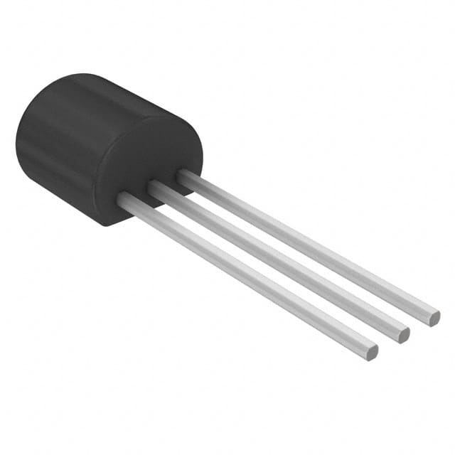
- Package: TO-92 package
- Essence: Silicon-based semiconductor device
- Packaging/Quantity: Typically available in reels or tubes containing multiple units.
Specifications
- Maximum Drain-Source Voltage: 35V
- Maximum Gate-Source Voltage: ±25V
- Continuous Drain Current: 350mA
- Power Dissipation: 625mW
- Operating Temperature Range: -55°C to 150°C
Detailed Pin Configuration
The J113_D26Z features three pins: Gate (G), Drain (D), and Source (S). The pinout configuration is as follows: - Gate (G): Input terminal for controlling the transistor's conductivity. - Drain (D): Output terminal through which the current flows. - Source (S): Terminal connected to the substrate and serves as the reference point for the FET.
Functional Features
- High input impedance allows for minimal loading of preceding stages.
- Low output impedance enables efficient signal transmission to subsequent stages.
- Voltage-controlled operation facilitates precise circuit control.
Advantages and Disadvantages
Advantages
- High input impedance enhances circuit performance.
- Low output impedance ensures effective signal transmission.
- Voltage-controlled functionality offers flexibility in circuit design.
Disadvantages
- Susceptible to static discharge damage if mishandled.
- Limited maximum voltage and current ratings compared to some alternative models.
Working Principles
The J113_D26Z operates based on the principle of field-effect modulation. When a voltage is applied to the gate terminal, it creates an electric field that modulates the conductivity between the drain and source terminals, allowing for the control of current flow.
Detailed Application Field Plans
The J113_D26Z finds extensive use in various applications, including: - Audio amplifiers - Signal switching circuits - Oscillator circuits - Voltage-controlled amplifiers
Detailed and Complete Alternative Models
Some alternative models to the J113_D26Z include: - 2N7000 - BS170 - J310 - BF256B
In summary, the J113_D26Z is a valuable field-effect transistor with distinct characteristics and versatile applications across different electronic circuits.
[Word Count: 410]
רשום 10 שאלות ותשובות נפוצות הקשורות ליישום של J113_D26Z בפתרונות טכניים
Sure, here are 10 common questions and answers related to the application of J113_D26Z in technical solutions:
What is J113_D26Z?
- J113_D26Z is a specific model of semiconductor component, commonly used in electronic circuits for various applications.
What are the key features of J113_D26Z?
- The key features of J113_D26Z include low on-resistance, high gain, and low noise characteristics, making it suitable for use in amplifiers and switching applications.
How is J113_D26Z typically used in technical solutions?
- J113_D26Z is often used in signal processing, audio amplification, and voltage regulation circuits due to its performance characteristics.
What are the typical operating conditions for J113_D26Z?
- J113_D26Z operates within a specified voltage and current range, typically around 30V and 350mA, making it suitable for a wide range of applications.
Can J113_D26Z be used in high-frequency applications?
- Yes, J113_D26Z can be used in high-frequency applications such as RF amplifiers and oscillators due to its low noise characteristics.
Are there any specific considerations when designing with J113_D26Z?
- Designers should consider the thermal management and proper biasing of J113_D26Z to ensure optimal performance and reliability.
What are the typical alternatives to J113_D26Z?
- Alternatives to J113_D26Z include similar JFETs or MOSFETs with comparable specifications, depending on the specific requirements of the application.
Can J113_D26Z be used in battery-powered devices?
- Yes, J113_D26Z's low on-resistance and low power consumption make it suitable for use in battery-powered devices, helping to extend battery life.
What are the common pitfalls to avoid when using J113_D26Z?
- Common pitfalls include exceeding the maximum ratings, improper biasing, and inadequate heat dissipation, which can lead to device failure.
Where can I find detailed application notes for using J113_D26Z in technical solutions?
- Detailed application notes for J113_D26Z can be found on the manufacturer's website, providing guidance on circuit design, layout, and best practices for integration.
I hope these questions and answers provide a good overview of the application of J113_D26Z in technical solutions! If you have any more specific questions, feel free to ask.