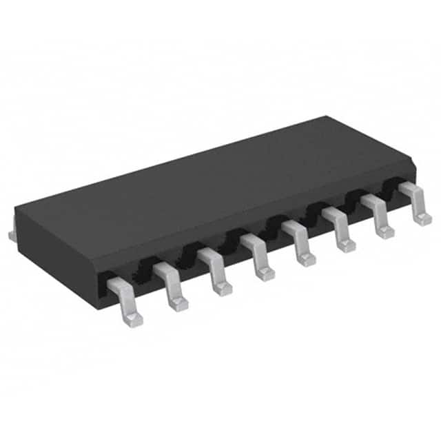
74HC138D,652
Product Overview
Category
The 74HC138D,652 belongs to the category of integrated circuits (ICs).
Use
This IC is commonly used in digital electronics for decoding applications.
Characteristics
- High-speed operation
- Low power consumption
- Wide operating voltage range
- Compatibility with various logic levels
Package
The 74HC138D,652 is available in a small outline package (SO) with 16 pins.
Essence
The essence of this product lies in its ability to decode binary inputs into multiple output lines, making it suitable for addressing and selection purposes.
Packaging/Quantity
The 74HC138D,652 is typically packaged in reels or tubes, with a quantity of 2500 units per reel/tube.
Specifications
- Supply Voltage: 2V to 6V
- Input Voltage: -0.5V to VCC + 0.5V
- Output Voltage: -0.5V to VCC + 0.5V
- Operating Temperature Range: -40°C to +125°C
- Maximum Propagation Delay: 25 ns
Detailed Pin Configuration
- GND (Ground)
- A0 (Address Input 0)
- A1 (Address Input 1)
- A2 (Address Input 2)
- /G1 (Enable Input)
- Y0 (Output 0)
- Y1 (Output 1)
- Y2 (Output 2)
- Y3 (Output 3)
- Y4 (Output 4)
- Y5 (Output 5)
- Y6 (Output 6)
- Y7 (Output 7)
- VCC (Supply Voltage)
- /G2A (Enable Input)
- /G2B (Enable Input)
Functional Features
The 74HC138D,652 is designed to decode a three-bit binary input into eight mutually exclusive outputs. It utilizes the enable inputs (/G1, /G2A, and /G2B) to control the decoding process. The outputs are active low, meaning they are inverted versions of the decoded inputs.
Advantages and Disadvantages
Advantages
- High-speed operation allows for efficient decoding in time-critical applications.
- Low power consumption makes it suitable for battery-powered devices.
- Wide operating voltage range ensures compatibility with various systems.
- Compact package size enables space-saving designs.
Disadvantages
- Limited number of address inputs restricts the range of decoding possibilities.
- Inverted output logic may require additional circuitry for certain applications.
Working Principles
The 74HC138D,652 operates based on the principle of combinational logic. The three address inputs (A0, A1, and A2) determine which output line will be activated. The enable inputs (/G1, /G2A, and /G2B) control the overall decoding process. When the appropriate combination of address inputs is applied and the enable inputs are active, the corresponding output line is selected.
Detailed Application Field Plans
The 74HC138D,652 finds application in various fields, including: - Address decoding in microcontrollers and microprocessors - Memory selection in digital systems - Multiplexing and demultiplexing operations - Data routing and signal selection in communication systems
Detailed and Complete Alternative Models
Some alternative models that offer similar functionality to the 74HC138D,652 include: - 74LS138 - CD74HC138 - SN74HC138 - MC74HC138
These alternatives can be considered based on specific requirements and availability.
Word count: 450 words
רשום 10 שאלות ותשובות נפוצות הקשורות ליישום של 74HC138D,652 בפתרונות טכניים
Sure! Here are 10 common questions and answers related to the application of 74HC138D,652:
Q: What is the 74HC138D,652? A: The 74HC138D,652 is a 3-to-8 line decoder/demultiplexer IC that converts binary information from three input lines into eight output lines.
Q: What is the purpose of using a 74HC138D,652 in a technical solution? A: The 74HC138D,652 is commonly used to expand the number of output pins available on a microcontroller or other digital device, allowing it to control multiple devices or components.
Q: How does the 74HC138D,652 work? A: The IC uses three input lines (A0, A1, and A2) to select one of the eight output lines (Y0-Y7) based on the binary value applied to the inputs.
Q: What is the maximum voltage the 74HC138D,652 can handle? A: The 74HC138D,652 can handle a maximum voltage of 5.5V.
Q: Can the 74HC138D,652 be used with both TTL and CMOS logic levels? A: Yes, the 74HC138D,652 is compatible with both TTL and CMOS logic levels.
Q: How much current can each output pin of the 74HC138D,652 source or sink? A: Each output pin of the 74HC138D,652 can source or sink up to 25mA of current.
Q: Can the 74HC138D,652 be cascaded to increase the number of outputs? A: Yes, multiple 74HC138D,652 ICs can be cascaded together to increase the number of outputs available.
Q: What is the power supply voltage range for the 74HC138D,652? A: The power supply voltage range for the 74HC138D,652 is typically between 2V and 6V.
Q: Can the 74HC138D,652 be used in both digital and analog applications? A: No, the 74HC138D,652 is specifically designed for digital applications and should not be used in analog circuits.
Q: Are there any specific precautions to take when using the 74HC138D,652? A: It is important to ensure that the input voltage levels are within the specified range and to avoid exceeding the maximum current ratings of the IC. Additionally, proper decoupling capacitors should be used to stabilize the power supply.


