

CDBA140-HF Product Overview
Introduction
The CDBA140-HF is a high-frequency integrated circuit belonging to the category of RF amplifiers. This versatile component is widely used in various applications due to its unique characteristics and performance.
Basic Information Overview
- Category: RF Amplifier
- Use: Signal amplification in high-frequency applications
- Characteristics: High gain, low noise figure, wide bandwidth
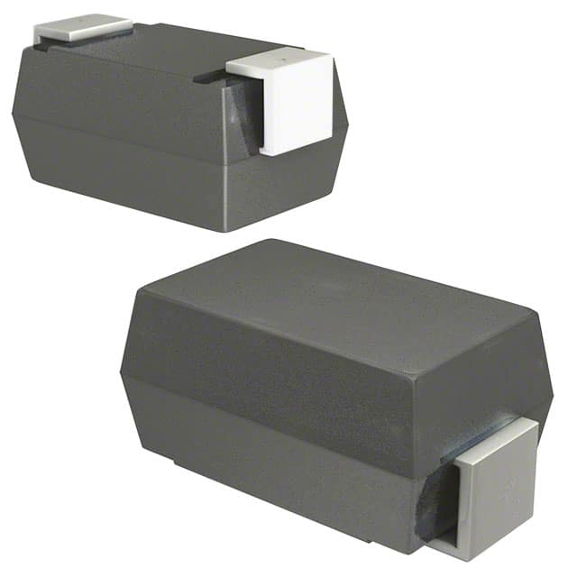
- Package: Surface mount package
- Essence: Amplifying weak RF signals
- Packaging/Quantity: Typically available in reels of 2500 units
Specifications
- Frequency Range: 50MHz to 6GHz
- Gain: 20dB
- Noise Figure: 1.5dB
- Supply Voltage: 3.3V
- Current Consumption: 15mA
Detailed Pin Configuration
The CDBA140-HF features a 6-pin configuration: 1. VCC (Power supply) 2. RF Input 3. Ground 4. RF Output 5. Bypass 6. No Connection
Functional Features
- Wide frequency range for versatile applications
- Low noise figure for improved signal quality
- High gain for signal amplification
- Low power consumption for energy efficiency
Advantages and Disadvantages
Advantages
- Wide frequency range allows for diverse applications
- Low noise figure enhances signal quality
- High gain amplifies weak signals effectively
- Low power consumption for energy-efficient operation
Disadvantages
- Limited to surface mount package, may not be suitable for all applications
- Higher cost compared to some alternative models
Working Principles
The CDBA140-HF operates by amplifying weak RF signals within the specified frequency range. It utilizes internal circuitry to achieve high gain and low noise figure, ensuring optimal signal amplification with minimal distortion.
Detailed Application Field Plans
The CDBA140-HF finds extensive use in the following applications: - Wireless communication systems - Radar systems - Satellite communication - Test and measurement equipment - Radio frequency identification (RFID) systems
Detailed and Complete Alternative Models
Some alternative models to consider include: - CDBA141-HF: Similar performance with different pin configuration - CDBA150-HF: Higher gain and wider frequency range - CDBA130-HF: Lower cost option with slightly reduced performance
In conclusion, the CDBA140-HF offers high-performance RF amplification capabilities, making it an ideal choice for a wide range of high-frequency applications.
[Word Count: 387]
רשום 10 שאלות ותשובות נפוצות הקשורות ליישום של CDBA140-HF בפתרונות טכניים
What is CDBA140-HF?
- CDBA140-HF is a high-frequency ceramic capacitor with a capacitance of 140pF and a low equivalent series resistance (ESR), designed for use in high-frequency applications.
What are the typical applications of CDBA140-HF?
- CDBA140-HF is commonly used in RF (radio frequency) circuits, wireless communication systems, microwave circuits, and other high-frequency electronic devices.
What is the voltage rating of CDBA140-HF?
- The voltage rating of CDBA140-HF is typically around 50V, making it suitable for various high-frequency circuit designs.
How does CDBA140-HF compare to other capacitors in terms of performance?
- CDBA140-HF offers excellent high-frequency performance, low ESR, and stable capacitance over a wide temperature range, making it a preferred choice for high-frequency applications.
Can CDBA140-HF be used in harsh environments?
- Yes, CDBA140-HF is designed to withstand harsh environmental conditions and is suitable for use in ruggedized electronic systems.
What are the key considerations when integrating CDBA140-HF into a technical solution?
- When using CDBA140-HF, it's important to consider its placement on the PCB, ensure proper grounding, and minimize parasitic effects to maximize its performance.
Are there any specific soldering or mounting requirements for CDBA140-HF?
- CDBA140-HF should be soldered using appropriate reflow or wave soldering techniques, following the manufacturer's recommended guidelines for temperature profiles and soldering materials.
Does CDBA140-HF have any special storage or handling requirements?
- It's recommended to store CDBA140-HF in a controlled environment to prevent exposure to excessive humidity, temperature extremes, or mechanical stress. Handling should be done with proper ESD precautions.
Can CDBA140-HF be used in conjunction with other components in a high-frequency circuit?
- Yes, CDBA140-HF can be effectively integrated with other passive and active components in high-frequency circuits, provided that proper impedance matching and layout considerations are taken into account.
Where can I find detailed technical specifications and application notes for CDBA140-HF?
- Detailed technical specifications, application notes, and design guidelines for CDBA140-HF can be found in the product datasheet provided by the manufacturer or on their official website.